AnnexRDS Getting Started Guide
(for the ESP32S3 – S3V Zushi)
AnnexRDS is an advanced OTA based system that utilizes the the Basic language for programming. All coding is done over the air (OTA). The S3V Zushi supports the extensize range of AnnexRDS capabilities, including VGA, USB input devices and I2S Audio. In this getting started guide we will work through the process of setting up your 3SV board with AnnexRDS.
1) Connect the S3V Zushi to your computer (e.g., your PC) using a USB-C cable.
2) Ensure the switch on the Zushi is set to PRG (not USB). The initial setup of AnnexRDS on an S3V requires a direct connection to the PC. All subsequent programming and setup can be performed via the web interface.
3) Press the [BOOT] button on the S3V, and while holding the [BOOT] button down, simultaneously press and release the [RESET] button. This will put your S3V Zushi board into bootloader mode.
4) On your PC open this link in a browser: https://cicciocb.com/.
5) Click [Web Installer].
6) In your web browser click [Connect].
7) Select your board. Your S3V board will be indicated as USB JTAG/serial debug unit (COM18), though the exact naming of the board and the specific COM port information will be different depending on your Operating System and how it identifies serial devices.
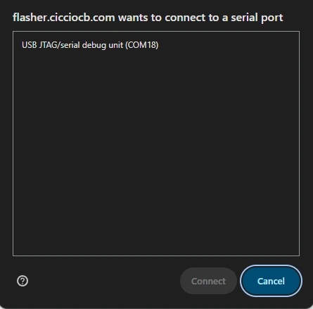
8) Click [Connect].
9) Unless your S3V is equipped with 16MB of Flash, select 8MB in the [Flash Size] dropdown list. 8MB is the standard size for Flash on the vast majority of S3V boards.
10) Click the [Set Config] button.
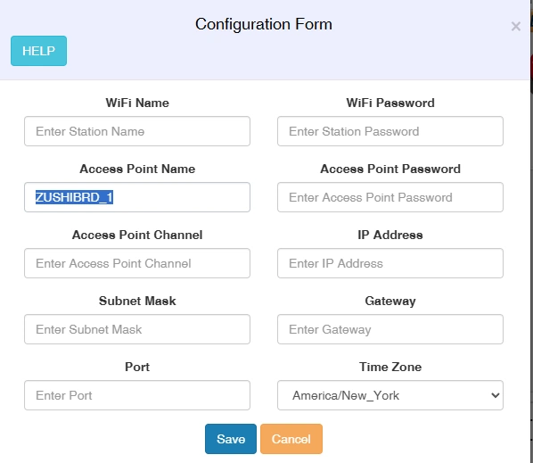
11) The Configuration Form enables setting a range of Wi-Fi settings and also Time Zone information. These settings can also be changed later in Basic if so required (as described in the comprehensive AnnexRDS help system).
12) In the Configuration Form enter ZUSHIBRD_1 as the Access Point Name. Feel free to change the AP name as required for your scenario.
13) Click [Save].
14) Click [Select Firmware].
15) Select Annex32-S3_DMT_LVGL_HID_OTG_ATS_2.99.27_qio_opi.bin
Note: Later version may be available. G
https://raw.githubusercontent.com/espressif/arduino-esp32/gh-pages/package_esp32_index.json
Exit and restart Arduino. Install the latest ESP32 device library using Arduino’s Board Manager via the Tools menu in Arduino. The ESP32 library should be updated periodically.
Using Arduino
You will need to ensure that the BZBoard S3V is in a programmable mode prior to uploading your sketch. On your BZBoard press and hold the <BOOT (0)> button while pressing the <RESET (EN)> button. The BZBoard module should be identified in Arduino as an ESP32S3 Dev Module. If not, please select this using the Boards menu.
You can verify the module is being correctly detected in Arduino by checking the Port and Info options on the Tools menu. This is the correct info for the Neuron:
BN: ESP32S3 Dev Module
VID: 303a
PID: 1001
The module selected must be ESP32S3 Dev Module. Ensure that you have selected the correct module type and serial port before proceeding with programming your Zushi in Arduino!
We recommend using the following settings to configure your Neuron in Arduino|Tools:
For Arduino 2.3.10+

For the first sketch upload you may need to put the BZBoardS3V "Zushi" in Boot mode. Hold the <Boot Button (0)> and then Press and release the <Reset (EN)> button. This may result in the serial port changing.

Settings for Tools:
Board: "ESP32S3 Dev Module"
Port: Select the Correct Serial Port for the Neuron
-------------------------------------------
Use CDC on Boot: "Enabled'
CPU Frequency: "240Mhz (WiFi)"
Core-Debug Level: "None"
USB DFU On Boot: "Disabled"
// Note: Erase All might need to be enabled once if you have been using other firmware (e.g., AnnexRDS) //
Erase All Flash Before Sketch Upload: "Disabled"
Events Run On: "Core 1"
Flash Mode: "QIO 120Mhz"
Flash Size: "8MB (64Mb)"
JTAG Adapter: "Integrated USB JTAG"
Arduino Runs On: "Core 1"
USB Firmware MSC On Boot: "Disabled"
// Note Partition Schemes are Project Dependent If not sure, use 8M with spiffs //
Partition Scheme: Typically "8M with Spiffs"
PSRAM (enabled): "OPI PSRAM"
Upload Speed: 921600
Upload Mode: "USB-OTG CDC
USB Mode: "USB-OTG (TinyUSB)"
Tip
On the initial sketch upload it may be necessary to press the <RESET (EN)> button on the BZBoard S3V to activate the uploaded sketch. Subsequent sketch uploads should automatically perform the rebooting step. You may need to re-check the serial settings (and possibly restart Arduino in extreme cases) if you are unable to connect and upload a sketch to a On the initial sketch upload it may be necessary to press the <RESET (EN)> button on the BZBoard on the fist try. The process of uploading sketches becomes easier once the Arduino USB-OTG firmware has been installed on the BZBoard ; the BZBoard has “received” it’s first Arduino sketch successfully. If there are errors in the sketch upload process they will be indicated in the IDE (below the code window).
You can test your Zushi with the following “Blink” sketch:
// Blink Example

void setup() {
// initialize the blink pin
pinMode(47, OUTPUT);
}

// blink loop function runs forever

void loop() {
digitalWrite(47, HIGH); // LED ON
delay(1000); // wait for a second
digitalWrite(47, LOW); // LED OFF
delay(1000); // wait for a second
}
There are a number of VGA libraries that are compatible with the ESP32-S3 based BZBoard S3V. We would recommend starting with the Bitluni VGA library. The BZBoard S3V is pin compatible with Bitluni’s library. If you intend on using the 16Bit modes provided by Bitluni’s VGA library then remember to bridge the following pins in the Expander connector (4, 5, 15, 16, 17). In 8 bit these pins should be un-bridged. We recommend using the 640X480 mode for best performance and maximum compatibility with TVs/Monitors.

BrainBoardzTM and Plug and CodeTM
are Trademarks of BrainBoardz Inc. © Copyright, 2021